¶ Morpho UV Printer Open SDK and Open JIG Interface
Morpho Open SDK is the extension entry point of Morpho Open System for advanced users, makers, and third-party developers. The first publicly available capability is the Open JIG Interface, which is used to develop third-party jigs that can work with Morpho UV Printer mechanical positioning, electrical connection, or status interaction.
In the future, Open SDK may continue to evaluate capabilities such as stereo vision, spectrometer access, and printhead movement. Whether these capabilities will be opened, and to what extent, will depend on user demand, safety risk, machine reliability, and warranty impact. This document does not commit to a specific release timeline.
¶ Open Scope
Open JIG Interface is a 12-pin hardware interface reserved by the machine for third-party jigs. It provides 24 V power, ground, reserved communication, reserved jig in-position detection, and safety-related signals. This interface is suitable for powered jigs, jigs that require in-position recognition, jigs that work with platform mechanical positioning, and advanced jigs that may require communication or status interaction in the future.
This document only defines the initial public boundary. UART, GPIO, in-position detection, and software interaction logic are still subject to Morpho's later official interface documentation.
¶ Downloads and Materials to Be Confirmed
| Material | Current status | Description |
|---|---|---|
| Connector drawing | Subject to the official drawing | Connector model, pin orientation, plug/socket part numbers, and harness requirements should follow the official connector drawing. |
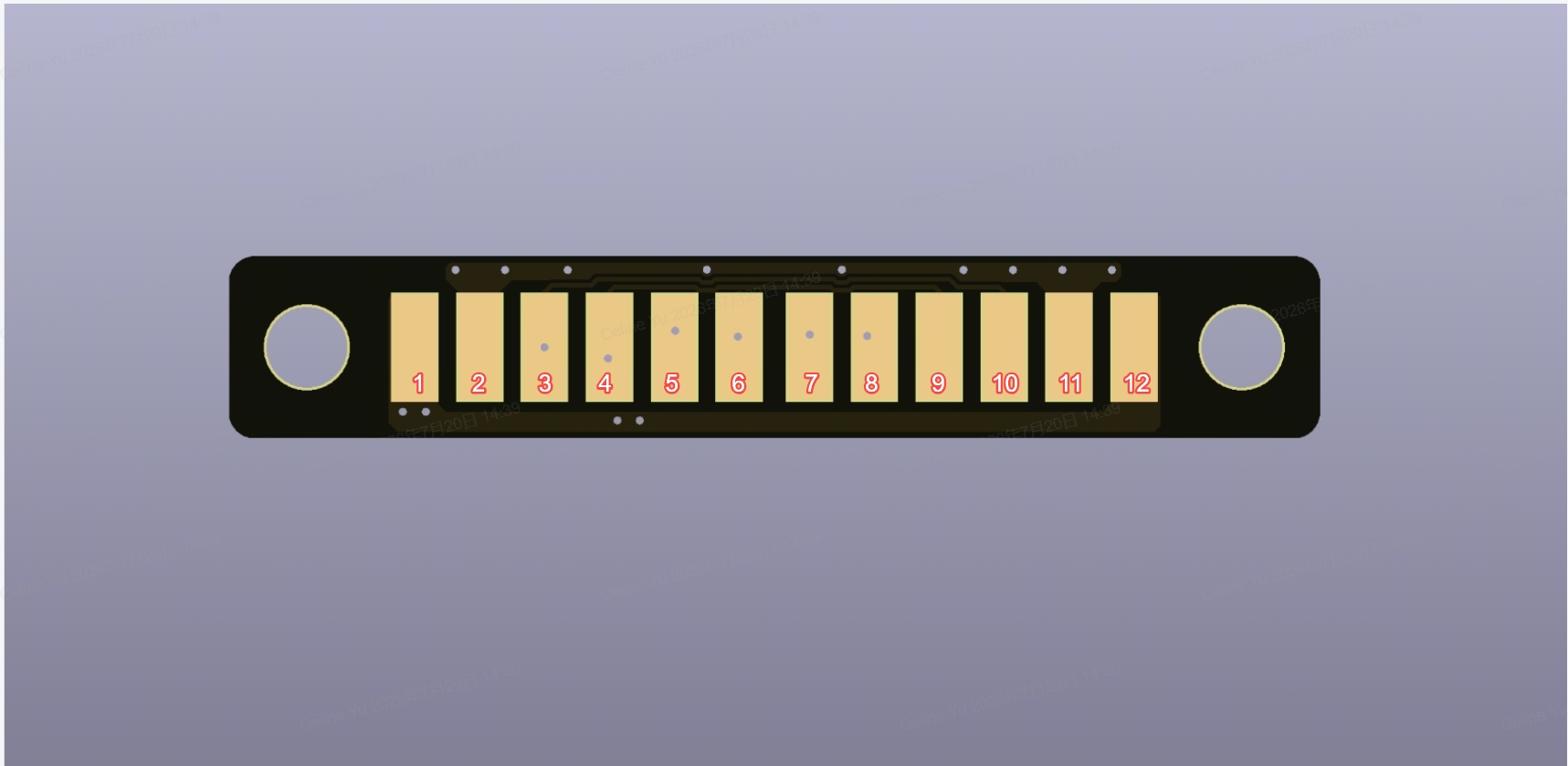
| JIG interface pinout diagram | To be inserted | Used to explain the machine-side interface location, pin numbering, and plug-in direction. |
| Reference board / Gerber files | To be confirmed | If provided later, they will serve as references for third-party jig control boards or adapter boards, but will not replace the developer's own electrical validation. |
| Custom jig base reference files | See the base plate structural design folder for A4 and A3 | Used to develop passive jigs, fixtures, or trays aligned with the base plate or A3 Printbed. |
¶ Interface Definition
| Pin | Signal | Description |
|---|---|---|
| 1 / 12 | VCC | 24 V, 0.7 A max |
| 2 / 11 | GND | Ground |
| 3 / 10 | UART TX | UART transmit line (machine side), JIG RX |
| 4 / 9 | UART RX | UART receive line (machine side) ,JIG TX |
| 5 | JIG in-position detection | Jig in-position detection |
| 6 | GPIO reserved | Reserved GPIO |
| 7 | GPIO reserved | Reserved GPIO |
| 8 | Anti-collision laser trigger signal | Emergency-stop / anti-collision related signal output from the machine to the jig |
The JIG interface provides 24 V power with a maximum current of 0.7 A. Third-party jigs must not exceed this current and must not back-feed voltage into VCC. Loads such as motors, heaters, fans, and electromagnets should only be connected when the jig has independent internal drive, protection, and isolation design. Jigs exceeding 24 V / 0.7 A must use an independent external power supply and must ensure that they do not affect the machine interface in reverse.
The detailed logic of UART TX, UART RX, JIG in-position detection, and reserved GPIO is not defined in this document. Before an official protocol is released, do not assume UART baud rate, data format, or protocol frames. Do not drive reserved GPIO by yourself, and do not design production jigs based on unofficial test results.
Pin 8 is the Anti-collision laser trigger signal output from the machine to the jig. It is an anti-collision / emergency-stop related signal. This signal is not a general-purpose control interface for third-party jigs. Third-party developers must not access, rewire, shield, simulate, or bypass it. Any design that attempts to bypass the door cover, safety interlock, UV protection, anti-collision detection, or emergency-stop logic is outside the support scope of Morpho Open SDK.
¶ Development Workflow
| Stage | What to do | Pass criteria |
|---|---|---|
| Mechanical validation | Install the jig without electrical connection, and confirm the platform interface, base plate interface, fixing method, and pickup/removal clearance. | The jig is installed stably and does not interfere with the printhead, carriage, camera, laser height measurement, maintenance area, or restricted area. |
| Electrical review | Before connecting to the machine, review operating voltage, peak current, continuous current, back-feed risk, surge, inductive load flyback, and short-circuit risk. | The load does not exceed 24 V / 0.7 A. If an external power supply or protection components are required, the independent design has been completed. |
| No-load power-on | Turn off the printer, connect the jig, power on the printer, and observe whether there are abnormal prompts, odor, noise, heating, or unexpected movement. | Continue only if there is no abnormal behavior. If any abnormality occurs, power off immediately and remove the jig. |
| In-position and safety check | Confirm jig status according to Morpho software prompts. Before communication and in-position detection logic are officially released, do not rely on unconfirmed behavior. | The software shows no blocking prompt, and the jig status matches the current task. |
| Dry run and anti-collision check | Without placing the final print object, run a dry run and path check. | The printhead path does not collide, cables are not pinched, the jig does not loosen, and no abnormal noise, odor, or temperature rise occurs. |
| First print validation | Use low-risk material, a low-height object, and a short task to validate positioning, print area, height detection, and pickup/removal convenience. | Print position is stable, the area is correct, and the jig remains fixed during the task. |
¶ Safety, Warranty, and Attribution
Open JIG Interface is an advanced developer mode. Connecting a third-party powered jig may affect machine safety, motion reliability, electrical reliability, and warranty assessment.
Incorrect wiring, loads exceeding 24 V / 0.7 A, inductive load flyback, external power back-feed, incorrect mechanical design, or bypassing safety interlocks, anti-collision protection, UV protection, or emergency-stop logic may cause machine damage or personal safety risks. If machine damage is caused by a third-party jig, incorrect wiring, over-specification load, or bypassing safety mechanisms, the related issue may fall outside the scope of Morpho's standard warranty. Machine issues unrelated to third-party jigs will still be handled according to Morpho's standard warranty terms.
If you design, publish, or sell third-party jigs, control boards, wiring harnesses, or related tools based on the Open JIG Interface, include the following attribution in your documentation:
Based on Morpho Open System.